| |
Collision Sensor Application Worksheet
(MS Excel)
For a successful application, the Protector chosen should be sized appropriately. To choose a model, consider the loads produced due to the static weight of the tooling, the inertial loads imposed by robot motion and the loads produced by the end-effector when performing its intended tasks. Once these loads are calculated and a specific model is chosen, the nominal pressure setting for the break-away point can be determined. The required air pressure setting must be readily available with ample adjustability. For example, a calculated pressure setting of 50 psi should have an adjustable range of 25-75 psi.
The selection process is as follows:
Figure 1 can be used to convert the forces acting on the end-effector tooling into the resulting moment, torque, and axial loads applied to the Protector. Use the diagram shown in Figure 1 and the formulas below to calculate the worst case applied loads for your application. All three load cases—Axial, Torque, and Moment—should be assessed for their Static, Dynamic, and Working force components.
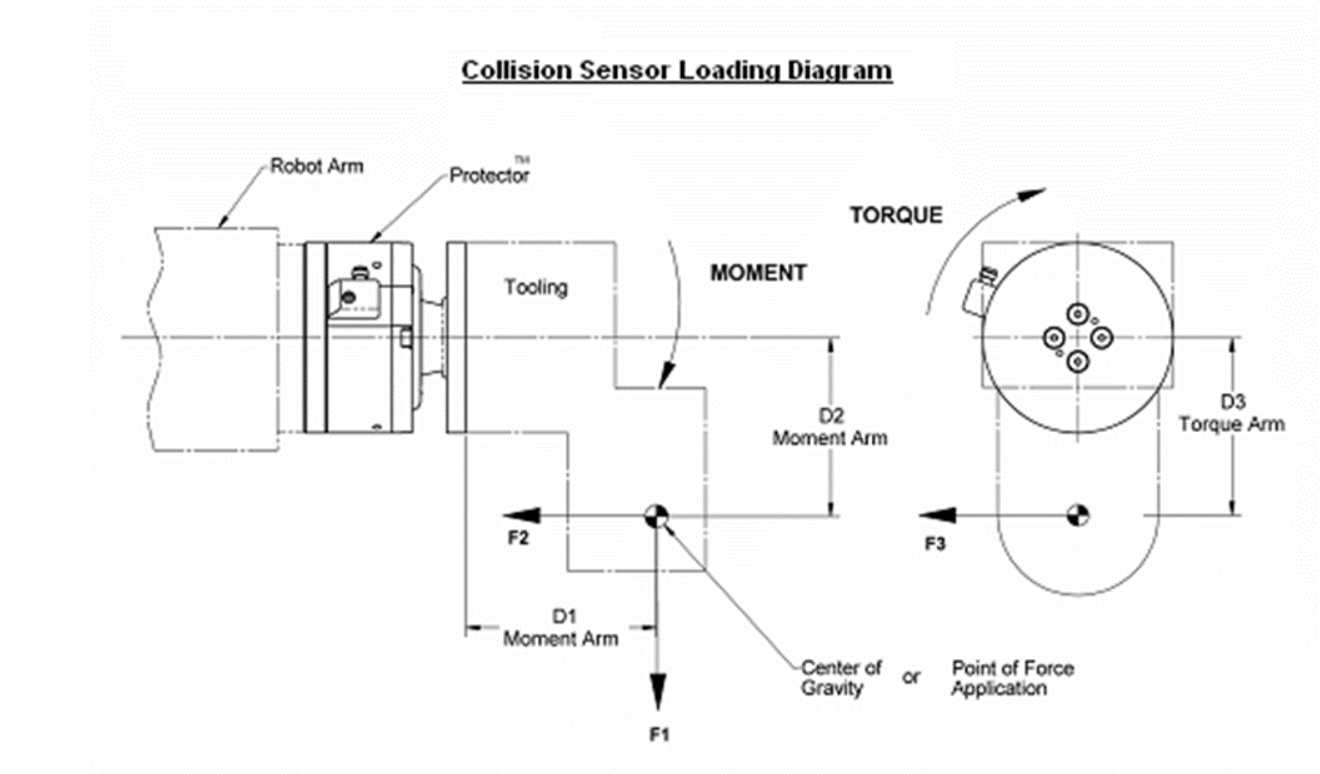 |
Not all of the component forces (Static, Dynamic, and Working) are present during all phases of the robot program. As a result, the worst case conditions for Axial, Torque, and Moment loads may occur at different times in the program.
|
|
Axial Load (F)
|
= |
F2
|
|
Torque (T)
|
= |
F3*D3
|
|
Moment (M)
|
= |
√( (F1*D1)2 + (F2*D2)2
)
|
(F1, F2, & F3 consist of the sum of their respective Static, Dynamic, and Working force components; and should always be positive for purposes of calculating break-away pressure settings.)
|
The load applied by tooling weight while the robot arm is idle. This includes the weight of all parts attached to the Protector, acting at the assembly’s center of gravity along the direction of gravity.
The inertial force imposed at the center of gravity of the tooling due to acceleration of the robot arm. This force acts in the direction opposite of motion. Dynamic forces are additive to static forces and must be carefully considered to ensure proper sizing of the protector.
Forces are generated at the tooltip under normal working conditions. If these forces and their location are known, they can be converted into loads on the Protector using the same technique.
Once the approximate loads are known from step one, pick a model that has a nominal moment and torque rating above the calculated loads under both dynamic and working conditions.
For a given model with known loads, the pressure setting required can be approximated from the following formula:
P = PM + PT + PF
Where PM, PT, and PF are the pressure components related to the moment, torque, and force load components expected at the break-away. PM, PT, and PF are calculated using the formulas in the following tables, where M, T, and F are the expected loads at the set pressure break-away.
(English Units: lb-in, psi, lb)
|
Click on any of the table headers to sort by the data in that column.
| Model | Moment | Torque | Axial |
| SR-48 | (M x 1.782) - 7.6 | (T x 1.519) - 2.3 | F x 0.926 |
| SR-61 | (M x 0.376) - 3.3 | (T x 0.444) - 6.3 | F x 0.462 |
| SR-81 | (M x 0.172) - 0.2 | (T x 0.168) - 0.8 | F x 0.233 |
| SR-82 | (M x 0.172) - 0.2 | (T x 0.168) - 0.8 | F x 0.233 |
| SR-101 | (M x 0.085) | (T x 0.081) - 2.8 | F x 0.147 |
| SR-131 | (M x 0.030) | (T x 0.033) - 1.7 | F x 0.085 |
| SR-176 | (M x 0.013) | (T x 0.012) - 2.4 | F x 0.045 |
| SR-221 | (M x 0.0052) | (T x 0.0065) + 7.3 | F x 0.029 |
|
(Metric Units: N-m, Bar, N)
|
Click on any of the table headers to sort by the data in that column.
| Model | Moment | Torque | Axial |
| SR-48 | (M x 1.0874) - 0.5 | (T x 0.9267) - 0.2 | F x 0.01435 |
| SR-61 | (M x 0.2294) - 0.2 | (T x 0.2708) - 0.4 | F x 0.00719 |
| SR-81 | (M x 0.1052) | (T x 0.1027) - 0.1 | F x 0.00361 |
| SR-82 | (M x 0.1052) | (T x 0.1027) - 0.1 | F x 0.00361 |
| SR-101 | (M x 0.0517) | (T x 0.0495) - 0.2 | F x 0.00228 |
| SR-131 | (M x 0.0183) | (T x 0.0199) - 0.1 | F x 0.00132 |
| SR-176 | (M x 0.0077) | (T x 0.0075) - 0.2 | F x 0.00070 |
| SR-221 | (M x 0.0032) | (T x 0.0040) + 0.5 | F x 0.00045 |
|
For an SR-81 with a moment of 100 lb-in, torque of 50 lb-in and an axial load of 20 lbs, and an acceleration of 2 G’s, the pressure setting is calculated as follows:
P = ((100*0.172) - 0.2) + ((50*0.168) - 0.8) + (20*0.233) + ((100*2*0.172) - 0.2)
= 17 + 7.6 + 4.66 + 34.2
= 63.46
A nominal air pressure setting of 63 psi is required.
|
|