|
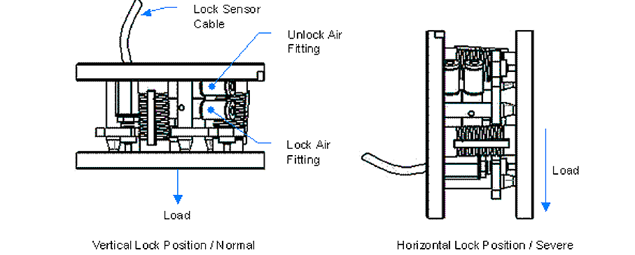
Units equipped with lock-up are recommended to use an air supply from 60 to 120 psi (4.1 to 8.3 bar). In severe locking conditions, the air supply can be adjusted to a maximum of 120 psi (8.3 bar). Lock-up is operated by applying air to the desired fitting (lock or unlock). The opposite fitting must be exhausted for the cylinder to operate correctly. The unit is recommended to be locked in the vertical position. This creates a normal locking condition. A severe locking condition occurs when the unit is locked in the horizontal position under a load. In such a condition, the load is being lifted by the lock-up mechanism (see figure below).
Please note that severe locking conditions will create above normal wear on the lock-up screw bushings. For the recommended lubrication periods for normal and severe locking conditions, see Section 7 - Maintenance of the Compensator Installation and Operation Manual.
Using a flow control valve to reduce the acceleration of the lock-up screw into the tool-side (bottom) plate will help to reduce wear on the lock-up screw bushing.
|
Lock Sensing Feature (Optional)
|
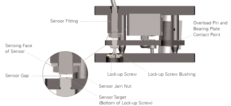
Lock sensing is achieved by monitoring the position of the lock-up screw. When air pressure is applied to the cylinder to lock the unit, the lock-up screw is pulled into the tool-side (bottom) plate. The lock-up screw enters the sensing range of the proximity sensor, sending a lock signal (see figure below).
|
|